Ok, so we know where we're mounting the Microsquirt ECU. And we know how much MS harness we have to work with. And we know the general wiring concepts and what pin housings and terminals we're going to use. But there's still some outstanding questions.
One issue is grounds. The MS needs two different grounds: a chassis one for the MS unit itself (it has two black chassis ground wires) and one back to the MS for the sensors. The chassis ground is pretty easy: there's a multi-pin ring terminal at a case half bolt in the back-middle of the engine. The engine grounds to the transaxle and there's a big ground strap on the back end of the transaxle to a stud on the chassis, and the battery negative wire goes to that same chassis stud. Soup. I can run MS, wideband controller, and ignition coil to that.
One issue is grounds. The MS needs two different grounds: a chassis one for the MS unit itself (it has two black chassis ground wires) and one back to the MS for the sensors. The chassis ground is pretty easy: there's a multi-pin ring terminal at a case half bolt in the back-middle of the engine. The engine grounds to the transaxle and there's a big ground strap on the back end of the transaxle to a stud on the chassis, and the battery negative wire goes to that same chassis stud. Soup. I can run MS, wideband controller, and ignition coil to that.
The sensor grounds require a bit more thought. Each sensor -- CPS, TPS, IAT, MPS, CLT -- needs to have a reference ground back to the Microsquirt itself through that sole sensor-ground wire. Five-wires-into-one presents a tad bit of a problem...do you splice them together? Do you create a ground block somewhere? What about my "no butt splices"?
On top of that many of those same sensors need access to a single +5V output wire from the MS box...again, splice them all together...? Sounds kludgy.
3/28/22 Update: Please read Part 11 Addendums. I no longer recommend using the Bussed Feedback Receptacles described below for the 5V sensor reference and ground. I instead discovered the SensorX Sensor Breakout Board which does it all for me, and can be neatly tucked into the harness. I changed the car from the below device to the SensorX. I'm leaving the info here because I still think they're pretty cool and could be useful for something else.

 I happened to learn about something really cool. Deutsch makes something called "Bussed Feedback Receptacles". These things are 2-, 4-, 8, and 12-way female pin housings that connect together wires within the male plug in various ways. So, for example, I could use a "12-Way Bussed Feedback Receptacles" that connects the left 6 wires together in one circuit, and the right 6 wires in another circuit! This was how I was going to do it! I could wire all five ground wires to one side of the male 12-way plug with one wire going to the MS ground wire, then all five +5V wires to the other side of the male 12-way plug with one wire going to the MS +5V wire! Each of those circuits would be connected together!
A perfectly elegant solution. You can even get mounting tabs for them (as I did) to mount somewhere convenient.
In the same manner, I needed to deliver 12V power to each of the four injectors, the IGN4 coil, and the wideband controller. Let's see...four injectors plus one plus one is six, one wire going to the relay is seven...sounds like I'll also buy an 8-way "Bussed Feedback Receptacle"!
Sensor 5V reference power and signal ground issue -- resolved.
So what size wire to use for the relayed-12V power items? I figured the injectors didn't need many amps, but the IGN4 might need as much as 15. I spent a lot of time looking through various sizing charts, and decided in the end to go with 14g for all of it. These are short runs so I'm not too worried with that decision. A single 25' roll of red wire for all of it. Though I do admit those little injector terminals did not like getting crammed with 14g wire...but I managed.
For reference, the whole factory D-Jet system, including Bosch coil, low impendance injectors, and the ECU and its sensors, all ran on a single 25A fuse. I'm actually impressed...
At this point I was ready to start cutting and terminating wires. I installed all the parts, all the sensors, lightly draped the MS wiring harness across it all, and grabbed a beer to stare at it...and had no idea how much work I had ahead of me. So I grabbed another beer and decided that first wire snip would be put off for another day of
 |
1 - TPS, fabbed bracket
2 - GM MAP, mounted on the tab where aux air valve was
3 - GM IAT, fabbed bracket, where cold start valve was (see adddendums, it was moved later)
4 - CPS mounted behind cooling fan housing
5 - VW IGN4 coil, fabbed plate where distributor was (see adddendums, it was moved later)
6 - FiveO high-impedance 280cc injectors, stock mounting location
7 - Wideband controller, mounted on vertical shroud ((see adddendums, it was replaced later)
8 - Roughly where Microsquirt ECU will mount on chassis
9 - Going all-Deutsch, with stamped pins
|
I mounted all that up, looked at the coiled MS wiring harness, and thought to myself..."what's gonna be the first wire you cut? 'Cause once you cut, you can't un-cut..."
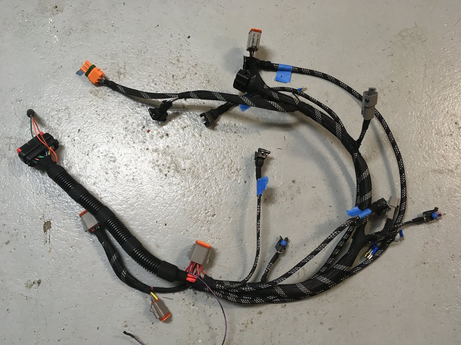
I'm'a gonna pull a Bob Villa on you and just show the final result. You can scroll down for some details.:


But this was a shat-ton of work; I probably have about 20 hours in it between design and implementation (could probably replicate it in 5). Some tips.
Highly useful tools:


TDC - Top Dead Center, the firing position for #1 cylinder
CPS - Crank Position Sensor, also known as CAS, Crank Angle Sensor
TPS - Throttle Position Sensor
MPS - Manifold Pressure Sensor
IAT - Intake air Temperature sensor
CLT - Coolant temp sensor
AFR - Air-Fuel Ratio
FLAPS - Friendly Local Auto Parts Store
CSV - Cold Start Valve
MS - Microsquirt

But this was a shat-ton of work; I probably have about 20 hours in it between design and implementation (could probably replicate it in 5). Some tips.
- Ensured all sensors and bussed receptacles were in their correct places and orientation;
- Separated the different MS wire functions and used Velcro straps to retain wires in desired routing;
- ID'd the wires I wasn't going to use (roughly half of them) and disassembled the MS connector and removed those wires entirely (put aside for future needs);
- Snipped off the obvious excess to minimize clutter;
- Worked from farthest point out, inward;
- Signals first, ground second, power last;
- Generous on strain to minimize wire fatigue;
- Terminated everything. Lots of crimped wires.
Highly useful tools:
- Very good wire cutter/stripper
- "W" crip connector. I used a ratcheting Weatherpack crimper from Eastwood
- Cheaper "w" connector tool to final-crimp wires and insulation strain-relief
- Deutsch pin and insert removal tool
- Deutsch pick removal tool
- Pin extractor tool - buy these, 'cause you know you're gonna need to remove a pin or two


So now it looks like it's just about time to install the engine into the car...well, after installing the clutch, stabbing the transaxle, installing the starter and wiring, putting on the engine frame and mounts, transaxle mounts, install an oil cooler...you know, just a few small things.
TDC - Top Dead Center, the firing position for #1 cylinder
CPS - Crank Position Sensor, also known as CAS, Crank Angle Sensor
TPS - Throttle Position Sensor
MPS - Manifold Pressure Sensor
IAT - Intake air Temperature sensor
CLT - Coolant temp sensor
AFR - Air-Fuel Ratio
FLAPS - Friendly Local Auto Parts Store
CSV - Cold Start Valve
MS - Microsquirt
Greg,
ReplyDeleteI am in the process of setting up CB Performances system on my 2056 and someone linked to your blog in a post I made about wiring. The CB Kit comes with a harness but I am hoping to reuse a few stock wires vs. running new stuff up into the interior and the front trunk.
Did you use the stock oil pressure sender on the top of the engine?
If so it looks as if that wire runs to the relay board through the harness. I am likely going to omit that harness and am wondering how others have gotten that signal to where it needs to go.
Hopefully what I am asking makes sense and you can share some experience.
I am using the stock wire for the oil pressure light in the fuel combo gauge. It does go through the stock relay plate and harness.
DeleteIt's a simple circuit, running up to the front, into the dash, and connecting to the light in the gauge. From there the other side of the circuit goes to keyed power. You can easily run a wire for it.
But why get rid of the stock relay plate and harness? Why not repurpose those circuits as needed? After all, it's already there for you...
Note in my wiring diagrams that I am running the Microsquirt, sensors, etc all through circuits that exist in the stock relay plate. The only thing I did was relay the injectors and ignition from battery power, but that relay is switched through that relay plate power source.
Leverage whatcha got!
Thanks for the reply. So I assume you scavenged the relay board connector form the original harness? My big debate with doing that is the possibility of moving the OE L-jet system to another car.
ReplyDeleteI did. There's a 4-pin connector on the relay plate that supplies power to the entirety of the D-Jet system; I simply tapped that for power for the Microsquirt, as well as control for the fuel pump.
Delete