On "Microsquirting" the Porsche 914 - Part 11, Addendums and Updates
Start Here for Part 1!!!
...or...
Back to Part 10
Lessons learned and subsequent changes made.
Figured I'd create a separate blog for "what I'm learning" and minor stuff. These are updated in reverse chromological order (latest ones first) so if you come back on occasion the newest ones will be on top.
3/30/26 Update
The 914 didn't get driven much in 2025, as I had the 968 diverting my attention. But yesterday was a sunny garage cleaning day and with the 914 sitting out in the driveway catching some rays I decided to take it for a short spin.
After cycling the key a couple times to get fuel through the feed/return circuit...it fired right up. and in fact I think it's driving as smooth as it ever has.
What a fantastic ride.
12/01/24 Update
I've decided to bail on the TB project...for a couple reasons.
One, I just can't dig up the motivation to start it. I got myself into a 968 in the Fall of '23 and have been working on that and not so much the 914 (the 914 is running fine!)
Two, with the light "EFI" cam I have in the engine, plus the stock exhaust, I don't think I would see a significant performance increase. It would be fun to see the difference, but I'm not motivated enough to be that curious.
So I sold off the parts I'd collected and we're just gonna enjoy it as-is for now. Sorry!
10/04/23 Update
Oh, this ain't fun. I never got to the TB project this year...
Short version: the car has been running like crap all year (spoiler, it wasn't because of the EFI). Took it out in May and it was fine, June it wasn't running right and I was busy so I parked it. July it wasn't running well at all and the CHT was going vertical; September it wasn't running, period. I tried timing (it was spot-on), another ignition coil (nothing), tested the CPS (ummm...no signal?) so I put it on the lift to visually inspect the CPS (you'll recall it's behind the fan housing). By sticking a flashlight from the side behind the fan housing it was clear that the CPS was spaced way too far away from the toothed gear. But light leveraging with a long screwdriver showed the bracket was tight...so that meant the CPS wheel somehow moved forward away from it...?
And THAT meant one thing: the crankshaft hub bolt was loose. I put a socket on it and yep, the bolt was loose.
Here's the big prob: it's a taper fit. There's a keyway there but not to hold it in place, only to clock it in the right place; the strength comes from the clamping on the taper itself. I compared the ignition timing marks on the pulley to a TDC mark I made on the flywheel (there's an inspection notch at the top of the transaxle) and yup, they didn't align, the marks were off from each other by about 25-30 degrees. No wonder the damned thing didn't run.
And that meant one other important thing: I'd sheared off the crankshaft key and the front hub was spinning on the crankshaft.
You can read the gory details - and the resolution - at this link on 914world.com.
What did I do? Maybe I blew it on the re-install after installing the CPS. But I'm sure I torqued it (I torque everything). I even rechecked my race car and it was slightly loose, too. I wonder if these tapers get chewed up slightly over time...
You Type 4 owners: go check that hub bolt torque now. It's easy, and it's supposed to be 23 ft-lbs. Even better, put Loctite 243 on it and retorque, and add that check to your regular maintenance schedule.
.jpg)
12/17/2022 Update
So how y'all doin'? Done your build yet?
I haven't done anything significant to the street car this year, except a few street-tuning runs here and there (I'm doing minor corrections now). I got myself into a big race crash in April in the Super Touring Civic Si that earned me a ride in an ambulance to visit tsk-tsking people in white coats. By the time I got signed off by my own doc to return to racing I had to scramble mid-summer to get in enough races (in another car, the other one was written off) so I could qualify for our big September championship.
Coupled to full-time work-from-home now, I really didn't go too many other places in '22.
However, winter beckons here in Connecticut, and minds start to wander. You know what that means: new project!
I've ordered a pair of 36mm (per hole) throttle bodies from The Dub Shop. Mario just started carrying these and I figured it was worth a try, just to see how well the D-Jet induction compares.
I'm thinking the conversion will be fairly straightforward: remove the D-Jet induction and install these TBs on generic Weber IDF manifolds (my buddy Chris Foley has a pair), install Weber IDF air filters (Chris again, natch), and install Tangerine's dual-throttle-cable system (and that's Chris again!) Best I can tell, the EV1 injectors will plug right into my harness, the included TPS will plug right in too, I can use the supplied IAT (same connector?), and all I need to do it find a place to mount the GM 1-bar MAP sensor (and of course it'll plug right in.)
I have yet to dyno the D-Jet conversion - I keep promising myself "soon". But I will do that so we have a good comparison of just how useful that D-Jet system is. Might surprise us, you never know!
Merry Christmas and Happy New Year, y'all!
10/18/2022 Update: New to tuning? Want to learn more?
DIY Autotune - SUPER guys - are offering a free guide, The EFI Tuners Guide – Learn How EFI works!
Highly recommended.
Winter 2021 Update: The MR2
Ed and I got involved in yet another race car project: and H Production Toyota MR2. One of the first things I did was look into replacing the stock ECU with a DIYAutotune "PnP", plug n ply system. It's a really cool bit of kit, in that you can simply plug it into the stock wiring harness and now you have all the tuning capability of the Megasquirt 2. It uses the same basic computing abilities of the Microsquirt so it's familiar. First time I saw one of these it was for the Miata, when SCCA racers were using it.
We got one for the MR2's 4AGE and it was truly "PnP". I uploaded the default 4AGE program and the car fired right up.
Of course, not being satisfied with that I modified the system to bypass the AFM. Then I decided to leverage the PnP's DB9 plug to add Coil on Plug (more on that in a sec). Then I decided to get really fancy and convert it to CPS and remove the distributor entirely (batch injection and wasted spark).
And it worked great. And I learned a bit more in the process.
Interestingly, as with the IGN4VW coil mounted on the engine of the 914, we started to experience problems with the COPs on the MR2; having experienced it before I concluded they were overheating and cutting out. Ultimately, we converted the MR2 to LS2 coils and that problem has now gone away...
The things you learn. Kakashi.
10/26/2021 Update: A Really Nice Trip
It was late October in New England, and a beautiful Fall weekend was looming. Clear skies, warm days, cool nights. I'd agreed to drive down to meet my buddy Ed at New Jersey Motorsports Park for a race weekend where I was to race his Super Touring car (a ~300whp 2008 Honda Civic with a Quaife sequential transaxle - one heck of a ride).
Anyway, I was about to pack up to leave for NJMP and since Ed was taking care of all the equipment at the track all I had to bring was my gearbag (suit, helmet, etc) and a personal bag for clothes (we "camp out" in the race car trailer). As I walked out of the house I looked around at the weather and thought...you know, this would be a great weekend for a 914 drive. But I'm about to drive five or so hours - each way - in New York and New Jersey traffic.
To heck with it, let's take the 914.
Now, if you remember back to Part 1 of this odyssey you'll recall that the motivation for this project was a lack of trust in the stock engine management system. Not because the design was flawed - DJet is actually a decent system, similar in concept to the Microsquirt - but because it was getting long in the tooth and I wanted to stop spending money on it (and let's be fair, I wanted to play with the MS).
So the idea that one could casually toss a pair of bags into a 45-yr-old car and just go off for a long weekend to the Jersey Shore seemed pretty ludicrous...yet I did exactly that.
I'm typing this afterward so you know I survived (don't you hate when the ending is ruined?) And, except for semis and Toyota Priuses (Prii?) looming over me in stop-and-go traffic, it was a non-event. The car started every time, ran great (smoother than I've ever remembered it), and turned heads everywhere. And I got around 28mpg average to boot.
I need to do that more often.
The 914 at NJMP paddock |

03/12/2021 Update: Adafruit K-Type Thermocouple Amplifier

I'm still using the CLT for warm-up tuning, but the CHT is now my Sensai for tuning.
2/27/2021 Update: High Oil Temps
Quick answer: the high oil temps problem seems to be resolved. The solution was a rebuilt engine. Coupled to that, the exhaust ticking is now gone. I'm wondering if the right side head had a crack...?
More compression, an overbore, and slightly-warmer camshaft so I'm re-tuning everything. I've also discovered the idle control settings where I can core the idle speed with ignition advance*; why did I not know about that before? Idle is now rock solid at 950RPM (though my stock tach is showing 1150; is there a Speedhut tach in my near future? -- Edit: yup, installed a Speedhut).
*Startup/Idle - Idle Advance Settings and Idle RPMs Advance Timing
1/21/2021 update: SensorX Board
Oh my, why wasn't I aware of this product before?
Back in Part 7 you may recall I described how I had designed my sensor connections, using Deutsch "Bussed Feedback Receptacles" to connect 5V power and sensor grounds. I still think it's a nice solution, especially if you want to easily de-pin something.
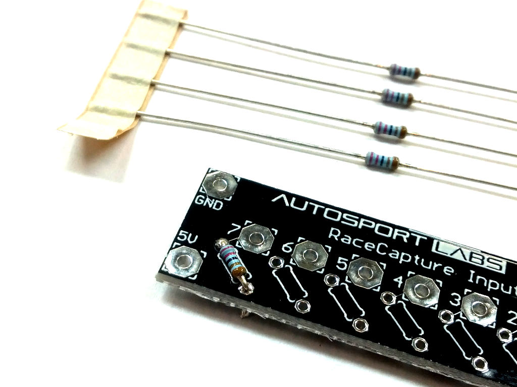
However, I've recently become aware of a product from Autosport Labs called the SensorX Sensor Breakout Board. This nifty little $10 product allows you to easily wire up eight sensors to a single board with your ECU's 5V source, ground, and inputs. Even better, it offers an easy place to insert your pull-up resistors, if needed.
I'm looking back at this wishing I knew about this last year. My 914 engine is coming out soon (I'm getting one rebuilt with some mods) and I bought two of these boards from PFTuning. When the 914's harness is removed I plan to replace the Deutsch busses with one of these.
Check out Autosport Lab's other stuff, they have some really cool solutions. Browse PF's catalog, too.
11/18/20 Update: Baseline Dyno
Got the 914 to a local dyno, to set a baseline. It's a DynaPack which is a hub-mounted dyno that controls the rate of RPM increase; my local vendor is Performance and Styling in Manchester CT. DynaPAck is my preferred dyno as you're not subject to wheel spin or tire pressire or anything like that, good for apples-to-apples comparisons.
Numbers were "OK", not terrible for a dead-stock 2L (as far as I know) Type IV engine: 96 torques at 2900RPM and 74 ponies at ~4400RPM. These are wheel (well, hub) numbers, of course.
Next step is to get an engine rebuild from FAT Performance with an overbore, more compression, and a tad more camshaft.

7/31/2020 update: Wideband Controller Failure
My original design used an Innovate LC-2 wideband controller with Bosch LSU 4.9 sensor. It wasn't too long into the game that I noticed the AFRs were not passing "the smell test" and were giving me inconsistent readings. In July the system quit working entirely.
Symptoms included erroneous readings, not powering on properly, and the dreaded "8 blinking LEDs" error, indicating that there was a problem with the sensor. The system would recalibrate properly each time, but upon engine startup would fail again. "The Internet" had a lot of comments on this, as it appears to be a common issue with this product. And, of course, the sensor is not covered under their warranty.
The premise seems to be that the LC-2 is driving the heating part of the sensor too hard and killing it. One of Innovate's "solutions" is to purchase a $90 spacer that heat-insulates the sensor from the exhaust stream. For a unit that originally cost $145.
The overiding response to many of these forum complaints was "get a Spartan Lambda Controller 3 from 14point7". $133 shipped, including a new 4.9 sensor. So I ordered one today and it should be installed next week. Watch this space...
Update: Innovate did agree to replace my sensor, and that has resolved my problems. However, I purchased the Spartan and it completely resolved my issues going forward. As of 2025 I'm still using the same Bosch sensor.
Ongoing Temperatures Battle
You've likely seen below where I've been battling under-trunk temperatures, especially with the oil cooling. I ended up buying a 4-probe BBQ temp sensor setup and doing some light evaluation. It's a lot hotter under there than I expected, and I learned that the duct I built made it worse. I think me and the car have come to "an agreement" and I've got satisfactory oil temps -- for now. Longer discussion of the process and results on 914World:
http://www.914world.com/bbs2/index.php?showtopic=347282
Intake Air Temperature, Part Deaux
 You'll note below that the IAT was not the problem with the cut outs...but it was still an issue. The engine compartment gets hot on this car. With the engine behind the vertical windshield there's a low-pressure area above the engine grill, right where you want high pressure, since air needs to go down into the engine compartment both for induction air and for engine cooling. A sub-optimal design. This car really should have been designed with a side air intake (or even both sides) like the first-gen Toyota MR-2 was...
 I removed the plastic under-grill rain tray and that helped a bit, but not enough. And moving the sensor (see below) helped a little but showed me that the plenum and air filter box are getting heat-soaked from the engine. They're bolted directly to the engine so I'm not clear how I'm going to resovle that...maybe some radient-reflective gold foil, yo...
I did effectively drop my IATs by 25-30F with this chintzy test setup. Haven't decided how I'm going to incorporate it permanently, as I need a way for water to collect and drain out before the airbox. Honda uses a plastic resonator in the fenderwell with a drain hole at its bottom, I may do something like that. I suppose I could drill a small drain hole at the lowest part of the metal airbox and that would do the same thing...after all, the air is pulling UP through the filter there so water ingestion is highly unlikely...and I think I'll modify one of the side grills to pull air from permanently.
3/28/22 Update: I adjusted the air filter housing so that the horn was spun 180 degrees and pointing toward the left. That required two other changes:
The mounts on the intake runners have to be loosed and moved so that the latches fit
The horn has to be shortened so that it does not contact the body
After that I clamped the black intake hose to the shortened horn and then using tye-wraps I ran a short section of it to the underside of the left intake grill on the side of the main grill (the part that stays fixed). So the car is now pulling cool intake air from outside.
Ignition Coil

After a period of driving, say a half hour or so, I started getting ignition mis-fires. At some point it would get so bad that the car was not drivable. Replacing the coil resolved it for a short time but then it would come back. I'll save you the dreary descriptions of the troubleshooting and just say that the problem ended up being heat: the coil was physically overheating from the ambient temperatures. My location of mounting it directly to the block was a bad choice.
I tye-wrapped the coil directly to the fan housing and drove it for an hour without problems. I'll need to fabricate an appropriate bracket for it.
Oil Cooler Fan
You may recall that during the MS install process I also installed an external oil cooler. Unlike some 914 oil coolers, which get installed in the nose for the ram/impact airflow, my cooler went under the rear trunk, and without a fan. I quickly found out, as ambient temps rose, that "no fan" wasn't gonna cut it; oil temperatures were running more than a tad hot. In fact, per my thermometer dipstick, I was seeing temps for 240+. Way too hot.
Installing a Derale 8" fan was easy enough, and it improved the issue. But how to control it? I could run it all the time with the key was on but that seemed inefficient; if the fan worked properly then the oil flow thermostat would effectively be controlling the temps (which is OK, I guess) but the fan is also running all the time when it doesn't need to.
Another option was to toss an inline thermostat switch on it, but the only ones I could find were 180, 190, or 200 degrees. Again, OK I guess but optimally I'd like more flexibility. The fan would probably be running almost all the time.
One other consideration is that I'm running a very small LiFePO4 battery, one with limited capacity (wanted to see how well it works; it does). If the alternator were to crap out then a fan running all the time may not give me the emergency reserve I need to get home. So maybe put the fan on a manual cut-off switch?
Then it hit me: use the Microsquirt! The MS allows extra sensor inputs and also offers output relay control. I can set the on and off temps to wherever I want them, and I can also make a condition that the battery voltage needs to be over a certain value.
My hangup is that I had initially removed those wires from the MS harness when I was a setting it up. That was short-sighted; I now needed the SPAREADC SPAREADC2 (spare inputs), and ALED and WLED wires (spare outputs).
But the one smart thing I did is make connectors everywhere so that the harness was easily removed.
So on one of my COVID-caused "Furlough Fridays" I removed the wiring harness and reinstalled those four wires to accept an oil temperature sensor input (SPAREADC) as well as use the ALED to control the fan relay (I also reinstalled SPAREDADC2 and WLED in the bundle for future use, maybe as a CHT input). Tested the ALED control with a "battery voltage>12.5" condition and it worked great. I installed the Race Technology oil temp sensor in an Improved Racing -10AN inline fitting and connected that into ADC6.
The MS cannot be programmed to recognize actual oil temps via a formula, but it does convert 0-5VDC to numerals 0-1203. I had to config the input for these "ADC" values and created a custom channel to convert to oil temps within TunerStudio (see .inc/cheater file here). I made the battery voltage a secondary "and" requirement (temperature over this "and" voltage over 12.5).
I can now control fan on-off based on temperature, and if my alternator craps out then the fan will stay off while I creep home on reduced load.
I'm still fighting temps though. Measuring the cooler output temps I'm still seeing 215+ under load on the highway. I've now boxed in the cooler intake and heat-sheathed the oil lines; I'm not clear what else I can do.
Update: it was a bum engine, maybe a crack in the head. An engine rebuild (with another core) resolved it.


Next up...CHT and alternate map?
I'm being pretty aggressive on ignition advance and leaning out the engine. But I don't know what that means to the engine; is it too aggressive? It runs fine on the street but what will happens if I decide to do a track day? These air-cooled engines are basically limited by CHT and EGT and I'm not measuring either.
I have one more input available and I've got this idea of installing a CHT sensor. The Sensor Connection offers one with 0-5V output. My thought is that I could install that system, input it into the Megasquirt, and monitor temps. If I find that my aggressive tuning results in extreme CHT then I can tune a secondary map and have it switch based on CHTs. CHTs running fine? Run the aggressive map. CHTs getting too hot? Switch to the lesser-aggressive map.
We'll see how motivated I am over the next few months.
Update: see above, CHT installed under #3 spark plug and routed into the MS.
Intake Air Temperature
I've noticed something funky happening as the ambient air temps are getting hotter: a new miss or some kind of load up at high temperatures and light throttle. It starts out as a stumble or miss and I glance over and see the AFR rolling back from extreme lean. If auto-tune is running then it starts to add a bunch of fuel in those areas. I only notice it at light cruise, 10% TPS or something like that, and if I go full throttle it goes away.
Back to the expert. Peter Florance quickly diagnosed that it's possibly due to either an overrun condition but more likely that my intake air temperature is showing really high and leaning out the engine. I had been noticing the high IAT; I figure it is because I have the sensor mounted on an aluminum plate directly to the intake manifold. It was probably heat-soaking, showing high temps. Per Peter's motivation, I moved the IAT sensor to the bottom side of the air cleaner, right where the snorkel is pulling in air. It's a good place and close enough to the current location (in the port for the D-Jet's cold start valve) that I won't even have to make any wiring changes. The old plate was plugged up with a 3/8" NPT plug.


Peter also sent an adjusted tune for it. We'll see how it goes! (Update: it went great! Peter's a sharp dude)
Comments
Post a Comment